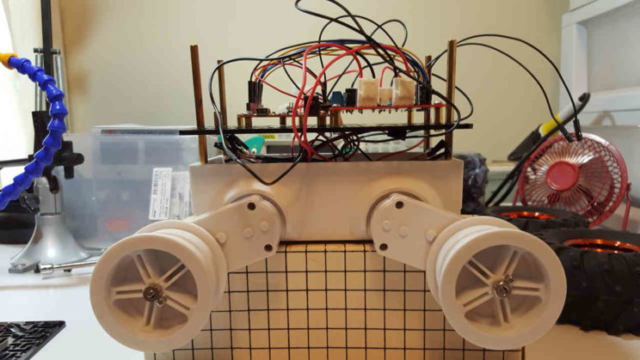
First things first. I have a platform with motors and wheels, so how do I make this thing move? My plan:
- connect motors to motor controller
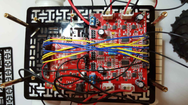
- connect motor controller to Arduino
- program Arduino to control motors
- connect Arduino to Raspberry Pi
- program Raspberry Pi to drive the rover in different ways (wifi, sensors, voice, etc.)
Rover 5 Chassis
This chassis has been around for a few years and came with 4 encoded motors, each with a gear ratio of 87:1. Each motor has a rated voltage of 7.2V, a stall current of 2.5A and an output shaft stall torque of 10Kg/cm. It has a rubber track on each side of the chassis and also includes a battery holder for 6x AA batteries.
The chassis doesn’t have any way to mount any electronics or peripherals so I’m using a couple of Rover 5 plates from Pololu. I already had standoffs, screws, nuts, etc. The plates have grooves cut into them to make it easy to find a place on the plate to attach something. The plates are a good, convenient idea to be able to make something quickly, but something a bit more solid would be better.
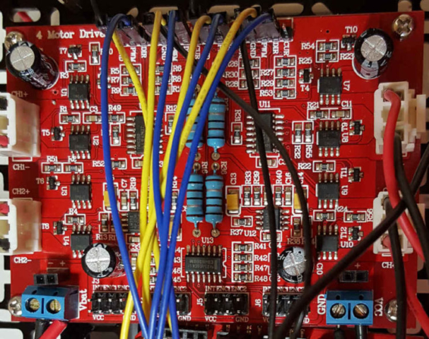
Rover 5 Motor Controller
For the Rover 5 chassis I decided to use the 4-channel motor controller that Dagu originally designed for it. I bought this a few years ago and set it aside and am only using it because I already have it. This board has no safety features and I have read of others destroying the board simply by attaching a battery to the motor circuits before attaching 5V to the logic circuits. This could be protected against that by using a software-controlled switch to turn on power to the motors only after the power is turned on to the logic circuits, but in the meantime I have to be careful to make sure that the logic circuits are powered before I connect the motor circuits. The only advantage to using this board over a more hardy motor controller is that this one has quad encoder mixing circuitry built into it. This will help save a bit of processing and a few pins on the Arduino, but the advantage is minimal since I will be using a Sparkfun Artemis ATP (with more available pins) and a Raspberry Pi.
Each channel is an FET “H” bridge rated for 4A stall current, with current monitoring and quad encoder mixing circuitry. Having 4 motor control channels make this controller more ideal for Mecanum or Omni wheels (since Mecanum wheels are controlled individually), and not as ideal for differential drive or skid steering using all 4 motors on this chassis. For 2 reasons:
- To attach 2 of these motors to 1 channel (for 1 side of the chassis) would exceed the stall current rating of the controller channel (2 * 2.5A > 4A). This could be controlled and protected with the current sensing on the board, but you wouldn’t get the full power benefit of the motors.
- There is no setting on the board to have 2 channels controlled in unison. I don’t know if this is something that some motor controllers offer.
Control of the Motor Control
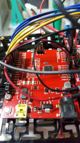
The plan is to use a Raspberry Pi 4 as the brains and an Arduino to control the mechanical parts. I first have to learn how to program the Arduino to control the motor controller, then learn how to use the Raspberry Pi to tell the Arduino what to do. Instead of a regular Arduino I plan on using a SparkFun Artemis ATP because it has more memory and processing power available but can be programmed as an Arduino.
The SparkFun Artemis uses 3.3V logic and the motor controller uses 5V logic. I forgot to order my 3.3V-5V logic convertors so for now I’m using a SparkFun Redboard (100% Arduino-compatible and uses 5V logic) to learn how to interact with the motor controller.
Each channel of the motor controller needs 1 pin of the Arduino to control the direction of the motor and 1 pin for PWM. Each channel also needs pins for the quad encoder, but today I am only learning to control the speed of the motors. On the Arduino, pins 3, 9, 10 and 11 are used to send PWM info for each wheel to the controller, and pins 4, 5, 6 & 7 to control the direction of each wheel. Here’s the initial setup for the Arduino:
// declare and assign PWM drive outputs
int front_left_drive = 3;  // motor controller ch 4
int rear_left_drive = 9;  // motor controller ch 3
int front_right_drive = 10;  //motor controller ch 2
int rear_right_drive = 11;  // motor controller ch 1
// declare and assign direction pins
int front_left_dir = 4;
int rear_left_dir = 5;
int front_right_dir = 6;
int rear_right_dir = 7;
void setup() {
  // initialize direction pins
  pinMode(front_left_dir, OUTPUT);
  pinMode(rear_left_dir, OUTPUT);
  pinMode(front_right_dir, OUTPUT);
  pinMode(rear_right_dir, OUTPUT);
}
On the Arduino Uno, the frequency for PWM is 490 Hz on the pins used (PWM on the Artemis can be set several times higher than that). The Arduino Uno uses 8-bit PWM, and 2^8=256, so the PWM values for the Arduino range from 0 to 255 (the Artemis uses 15-bit PWM, so the values for it will range from 0 to 32767).
The connectors coming from the motors only connect onto the motor controller board one way. I had assumed that each motor is wired to each connector in the same way, since there is no indication of front/rear or right/left on the board. The Arduino pin controlling the direction for a given motor has to be set high (1) for one direction and low (0) for the other direction in the Arduino code. If all motors are connected the same way, setting all 4 motors the same (all high or all low) should result in the motors on the left side turning one direction while the motors on the right side turn the opposite direction, since the motors on each side face opposite directions. If this was true, it would also mean that in order to move forward or backward, the direction output pins on one side would have to be set to HIGH while the direction output pins for the other side were set to LOW. However, when I ran some code set up that way to turn the motors, the front wheels turned the opposite of the back wheels.
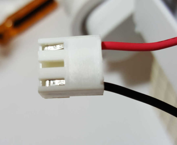
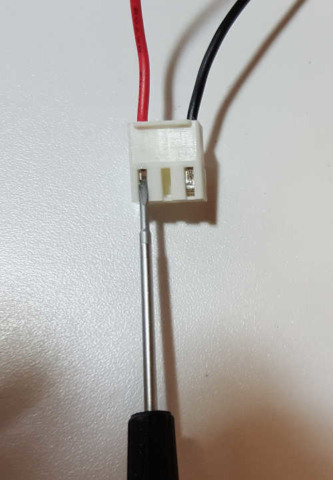
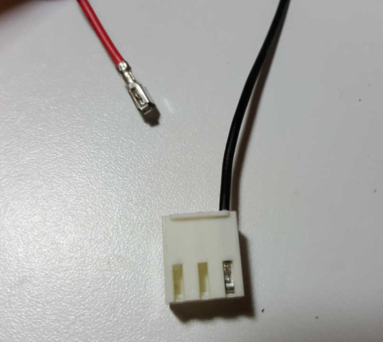
It makes sense to mount the motor controller board onto the chassis in a way that the motor channel on each corner of the controller board corresponds with the motor on that corner of the chassis. It also makes sense to have all 4 motor direction pins set to the same value to move one direction, i.e., all 4 direction pins set to high to move forward, and all 4 set to low to move backward. This was not possible because of the way the connectors were connected to the motor wires. So the simple solution was to mount the controller board to the chassis whichever way I prefer, and then switch the wires in the plug of any motor that wasn’t turning the way I wanted it to. All I had to do was use a small screwdriver to push down the metal “catch” through the gap on the connector and slide the wire out. The orientation of the wires on the plug do not matter since these are bi-directional DC motors that are controlled by changing the direction of the current going through them. They’re happy connected either way.
Power
So far I only have 3 items that need power: the motors, the motor controller, and the Arduino. The motors are powered through the motor controller, but the motor controller still needs a 5V power connection for the board to run, in addition to a 4.5V – 12V connection to power the motors. Later, when I switch from the Sparkfun Redboard Arduino to the Sparkfun Artemis ATP, I will implement a permanent power setup, either 2 different batteries (1 for motors and 1 for everything else) or a single battery with a voltage converter for the different voltages needed. In the meantime, to test the motors, I am using an a/c power supply to power the Arduino, and connecting the Arduino’s 5V output to the motor controllers 5V input. Then I connect a 7.2V battery to the motors. This allows me to test things, but since I have to make sure the motor controller has 5V before I connect the battery to the motors, I have to run a delay at the beginning of the code to allow me time to connect the battery to the motor controller before the program attempts to power the motors. It’s awkward, but it works.
The Arduino Code
I wrote the code to slowly speed up and slow down the motors, topping out at a PWM of 200, around 78% of full power (200/255 = 0.78). Here’s the simple code to test the setup:
/* initial testing of Rover 5 */
// declare and assign PWM drive outputs
int front_left_drive = 3;  // motor controller ch 4
int rear_left_drive = 9;  // motor controller ch 3
int front_right_drive = 10;  //motor controller ch 2
int rear_right_drive = 11;  // motor controller ch 1
// declare and assign direction pins
int front_left_dir = 4;
int rear_left_dir = 5;
int front_right_dir = 6;
int rear_right_dir = 7;
void setup() {
  // initialize direction pins
  pinMode(front_left_dir, OUTPUT);
  pinMode(rear_left_dir, OUTPUT);
  pinMode(front_right_dir, OUTPUT);
  pinMode(rear_right_dir, OUTPUT);
}
void loop() {
  // initialize direction pins to HIGH (forward)
  digitalWrite(front_left_dir, HIGH);
  digitalWrite(rear_left_dir, HIGH);
  digitalWrite(front_right_dir, HIGH);
  digitalWrite(rear_right_dir, HIGH);
  //give me 15 seconds to connect the battery
  analogWrite(front_left_drive, 0);
  analogWrite(rear_left_drive, 0);
  analogWrite(front_right_drive, 0);
  analogWrite(rear_right_drive, 0);
  delay(15000);
  // slowly speed up
  for (int pwm = 0; pwm <= 200; pwm = pwm + 10) {
    analogWrite(front_left_drive, pwm);
    analogWrite(rear_left_drive, pwm);
    analogWrite(front_right_drive, pwm);
    analogWrite(rear_right_drive, pwm);
    delay(500); // spend a half second at this speed
  }
  // slowly slow down
  for (int pwm = 200; pwm >= 0; pwm = pwm - 10) {
    analogWrite(front_left_drive, pwm);
    analogWrite(rear_left_drive, pwm);
    analogWrite(front_right_drive, pwm);
    analogWrite(rear_right_drive, pwm);
    delay(500); // spend a half second at this speed
  }
  // stop for 1 second
  analogWrite(front_left_drive, 0);
  analogWrite(rear_left_drive, 0);
  analogWrite(front_right_drive, 0);
  analogWrite(rear_right_drive, 0);
  delay(1000);

  //now drive backwards
  digitalWrite(front_left_dir, LOW);
  digitalWrite(rear_left_dir, LOW);
  digitalWrite(front_right_dir, LOW);
  digitalWrite(rear_right_dir, LOW);
  // slowly speed up
  for (int pwm = 0; pwm <= 200; pwm = pwm + 10) {
    analogWrite(front_left_drive, pwm);
    analogWrite(rear_left_drive, pwm);
    analogWrite(front_right_drive, pwm);
    analogWrite(rear_right_drive, pwm);
    delay(500); // spend a half second at this speed
  }
  // slowly slow down
  for (int pwm = 200; pwm >= 0; pwm = pwm - 10) {
    analogWrite(front_left_drive, pwm);
    analogWrite(rear_left_drive, pwm);
    analogWrite(front_right_drive, pwm);
    analogWrite(rear_right_drive, pwm);
    delay(500); // spend a half second at this speed
  }
  // give me 50 seconds to disconnect the battery
  analogWrite(front_left_drive, 0);
  analogWrite(rear_left_drive, 0);
  analogWrite(front_right_drive, 0);
  analogWrite(rear_right_drive, 0);
  delay(50000);
}
And here’s what that code does:
Nothing exciting here, but at least I know it works and I have a foundation to build on. My next step is to switch over to the Sparkfun Artemis ATP, which involves connecting and mounting voltage level shifters on the robot. I also need to get my power situation settled, 1 or 2 batteries attached to the chassis. Then I’ll write some functions in the code to make the motors easier to interact with.
